| SHS series socket welder | TPWC series Band saw |
| TPW series manual butt fusion machine | TPWG series workshop welding machine |
| TPWY series butt fusion machine | Series special tools |
| QZD series Auto-butt fusion machine | SHM series saddle fusion machine |
| Type | TPWG315 | |
| Materials for welding | PE,PP ,PVDF | |
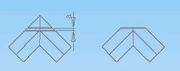
| Outside Diameter ranges | elbow (DN,mm) | 90 110 125 140 160 180 200 225 250 280 315mm |
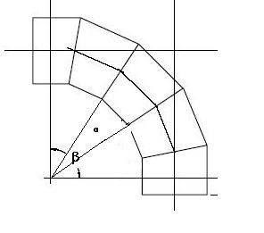
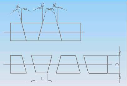
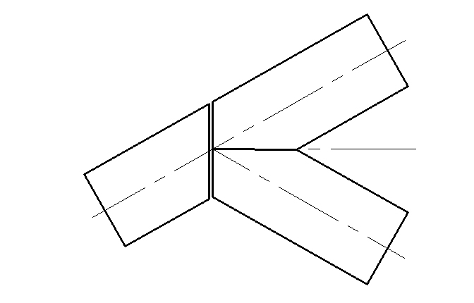
| tee (DN,mm) | 90 110 125 140 160 180 200 225 250 280 315mm | |
| cross (DN,mm) | 90 110 125 140 160 180 200 225 250 280 315mm | |
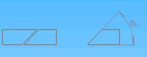
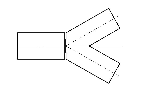
| Wyes 45°& 60° (DN,mm) | 90 110 125 140 160 180 200 225 250 280 315mm | |
| Environment temperature | -5~45℃ | |
| Hydraulic oil | 40~50(kinematic viscosity)mm2/s, 40℃) | |
| Power supply | ~380 V±10 % | |
| Frequency | 50 Hz | |
| Total current | 13 A | |
| Total power | 7.4 KW | |
| Include, heating plate | 5.15 KW | |
| Planing tool motor | 1.5 KW | |
| Hydraulic unit motor | 0.75 KW | |
| Insulating resistance | >1MΩ | |
| Max. hydraulic pressure | 6 MPa | |
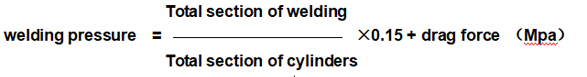
| Total section of cylinders | 12.56 cm2 | |
| Max. temperature of heating plate | 270℃ | |
| Difference in surface temperature of heating plate | ± 7℃ | |
| Undesired sound | <70 dB | |
| Oil tank Volume | 55L | |
| Total weight(kg) | 995 | |
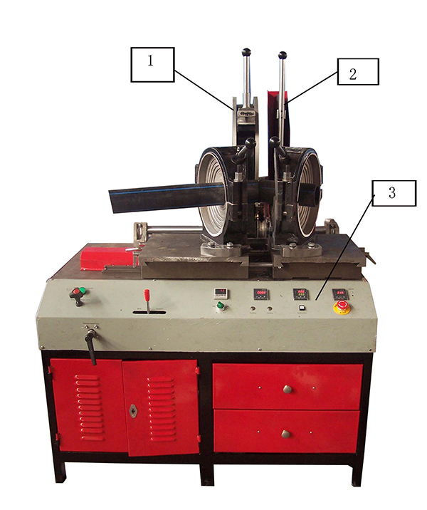
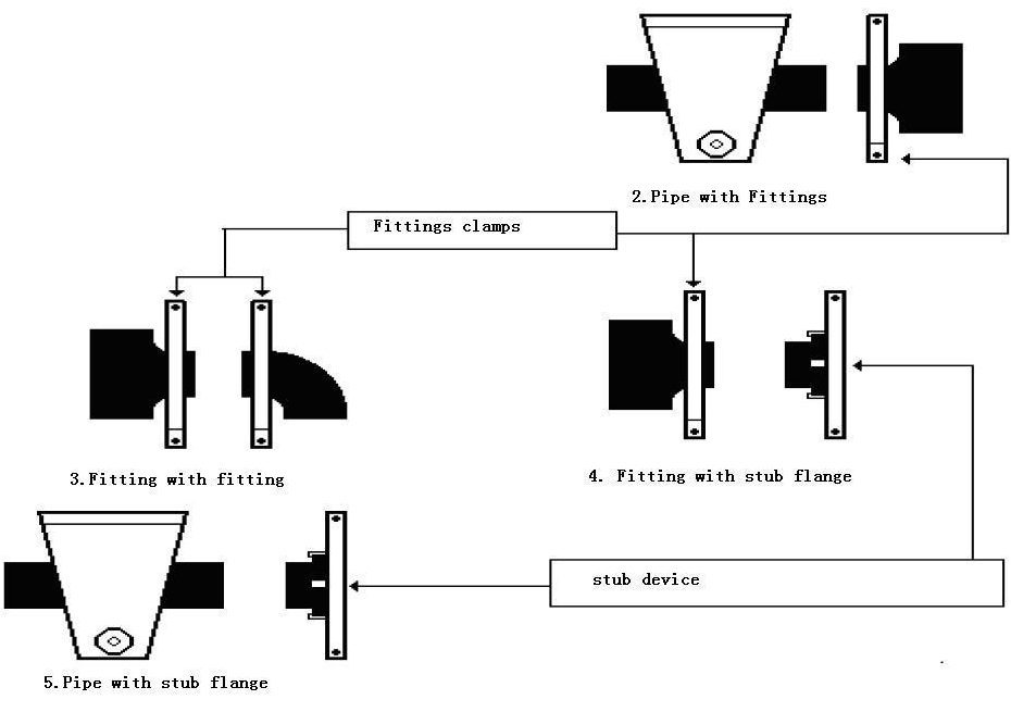
| 1. Planning tool | 2. Heating plate | 3. Operation panel |

| 1. Pressure Regulation Valve | 2. Pressure Relief Valve | 3. Oil Pump Working Indicator | 4. Direction Valve |
| 5. Digital Pressure Meter | 6. Planing Button | 7. Timer | 8. Soaking Time Button |
| 9. Temperature Control Meter | 10. Cooling Time Button | 11. Voltmeter | 12. Heating Switch |
| 13. Emergency Stop | 14. Buzzer |
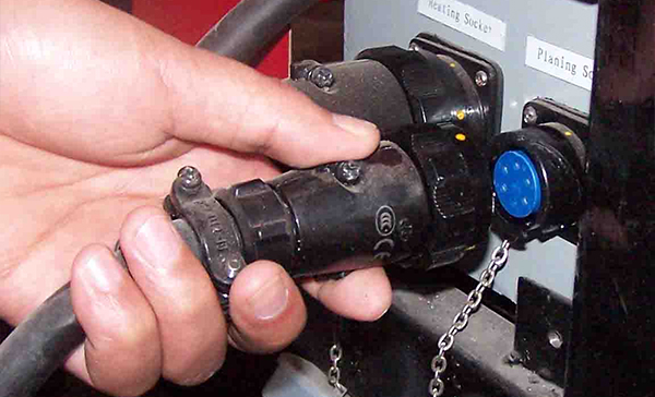
 6.2 Connection Make sure that the space is enough for putting the machine and keep the whole machine horizontal and assure the correct connection of all sockets, cables and hoses when installing the machine. 6.2.1 Connect the main machine to electrical box.
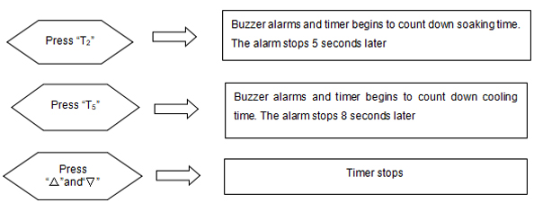
 6.2.2 Connecting the cable of the machine to power, which is three phases- five wires 380V 50HZ. For safety, the machine must be earthed from ground point of the machine. 6.2.3 Fill the filtered hydraulic oil. The height of the oil should be more 2/3 of the height of the scope of content gauge. Warning: Earthing must be finished by professional people.Follow all the safety rules on the machine. Untrained person is not allowed to operate the machine. 7.1 Power Close the ground fault interrupter 7.2 Start oil pump Start the oil pump to watch the rotating direction. If the pressure gauge has readings, the rotation is right, if not, exchange any two live wires. 7.3 Check and adjust drag pressure and move speed of drag plate. Working pressure of the system is 6 MPa. The joining pressure can be adjusted by pressure regulation valve located on the control panel. The planing pressure should be increased gradually, and keep it when continuous shavings appear (not too big). Feed speed of drag plate can be adjusted through the check valve (inside the base). 7.4 Clamps Installation Install left and right clamp seats (clamps for tees or elbows) according to fittings to be fabricated. 1) Fix them firstly by the lock pin attached with the machine; 2) Adjust the angle with the special location handle; 3) Tighten the lock screw with a wrench. If the elbow clamps needed to be used, press them tightly with the lock plate after adjust the angle. 7.5 Set specified temperature on temperature controller according to pipe welding process. (See section 7.10) 7.6 Before raise or lower the planing tool open the lock device on the handle. 7.7 Pipes positioning into the machine 7.7.1 Separate the clamps of the machine by acting on lever of direction valve 7.7.2 Position the pipes into the clamps and fasten them; the space between two pipe ends should be enough for planing tool. 7.7.3 Lock pressure relief valve, while close the two ends, turn the pressure regulation valve till the pressure gauge indicates fusion pressure, which is determined by the pipe materials. 7.8 Planing 7.8.1 Separate the clamps by acting on direction valve and fully open pressure relief valve. 7.8.2 Place the planing tool between the two pipes ends and switch on, approach the pipes ends towards the planning tool by acting on direction valve “forward”, and adjust the pressure regulating valve to keep suitable pressure till continuous shavings appear from the two sides.Note: 1) Thickness of the shavings should be within 0.2~0.5mm and it can be changed by adjusting the height of the planing tool. 2) Planing pressure should not exceed 2.0 MPa to avoid the damage of the planning tool. 7.8.3 After planing, Separate the clamps and remove planning tool. 7.8.4 Close the two ends to align them. If the misalignment exceeds 10% of the pipe thickness, improve it by loosening or tightening the upper clamps. If the gap between the ends exceeds10% of the pipe’s wall thickness, planing the pipe again till get the requirement. 7.9 Welding 7.9.1 Set the soaking time and cooling time according to the welding process. 7.9.2 After removing planing tool, place heating plate, Lock gradually pressure relief valve while pushing forward direction valve, which increases heating pressure to the specified fusion pressure(P1). The pipe ends stick to heating plate and the fusion begins. 7.9.3 When a small bead build up, push back the direction valve on the middle to keep the pressure. Turn swing check valve to lower the pressure to soaking pressure(P2) and then lock it quickly. Then push down the soaking time button to time. 7.9.4 After the soaking (the buzzer alarms), open the clamps by acting on the direction valve and remove heating plate quickly. 7.9.5 Join the two melted ends quickly and keep the direction valve on the “forward” for a short time and then push back to the middle position to keep pressure. At this time, readings in pressure gauge is the set fusion pressure (if not, adjust it by acting on pressure regulation valve). 7.9.6 Push down the cooling time button when cooling begins. After the cooling time elapses, the buzzer alarms. Relive the system pressure by acting on pressure relief valve, open the clamps and remove the joints. 7.9.7 Check the joint according to welding process standards. 7.10 Temperature controller and timer 7.10.1 Timer setting
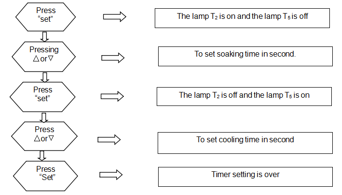
 7.10.3 Temperature controller setting 1) Press “SET” for more than 3 seconds till “sd” is shown in the upper window 2) Press “∧” or “∨” to change the value to specified temperature (press“∧” or “∨” continuously, the value will plus or minus automatically) 3) After setting, press “SET” to go back to monitoring and controlling interface
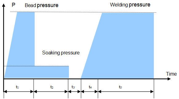
| Wall thickness (mm) | Bead height(mm) | Bead build-up pressure(MPa) | Soaking time t2(Sec) | Soaking pressure (MPa) | Change-over time t3(sec) | Pressure build -up time t4(sec) | Welding pressure(MPa) | Cooling time t5(min) |
| 0~4.5 | 0.5 | 0.15 | 45 | ≤0.02 | 5 | 5 | 0.15±0.01 | 6 |
| 4.5~7 | 1.0 | 0.15 | 45~70 | ≤0.02 | 5~6 | 5~6 | 0.15±0.01 | 6~10 |
| 7~12 | 1.5 | 0.15 | 70~120 | ≤0.02 | 6~8 | 6~8 | 0.15±0.01 | 10~16 |
| 12~19 | 2.0 | 0.15 | 120~190 | ≤0.02 | 8~10 | 8~11 | 0.15±0.01 | 16~24 |
| 19~26 | 2.5 | 0.15 | 190~260 | ≤0.02 | 10~12 | 11~14 | 0.15±0.01 | 24~32 |
| 26~37 | 3.0 | 0.15 | 260~370 | ≤0.02 | 12~16 | 14~19 | 0.15±0.01 | 32~45 |
| 37~50 | 3.5 | 0.15 | 370~500 | ≤0.02 | 16~20 | 19~25 | 0.15±0.01 | 45~60 |
| 50~70 | 4.0 | 0.15 | 500~700 | ≤0.02 | 20~25 | 25~35 | 0.15±0.01 | 60~80 |


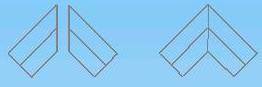


| u Visually check:round bead, good joint | 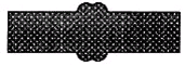 |
| u Narrow and fall bead. Too high pressure while welding |  |
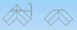
| u Too small bead. Pressure is not enough while welding |  |
| ◆ There is a ditch between the welding surfaces. Temperature is not enough or change-over time is too long while welding. | |
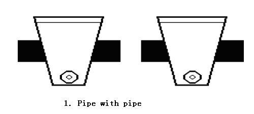
| ◆ High & low bead. Different heating time or fusion temperature causes that. |  |
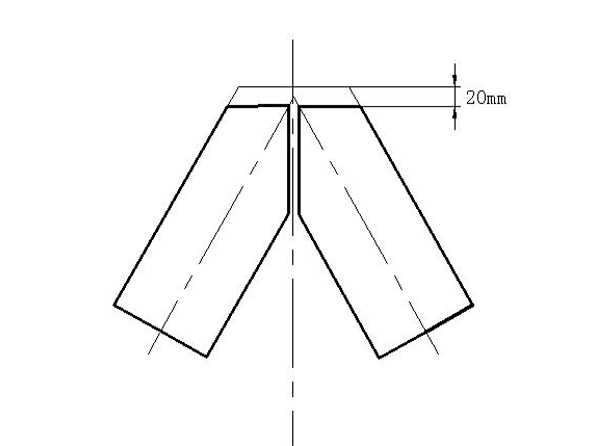
| ◆ Misalignment. Welding under the condition that the misalignment exceeds 10% of pipe wall thickness while align the two ends. |  |
| Malfunctions of hydraulic unit | |||||
| No | malfunction | analyzes | solutions | ||
| 1 | The motor does not work |
| |||
| 2 | The motor rotate too slowly with abnormality noise |
| than 3 MPa
| ||
| 3 | The cylinder works abnormally |
| to outgo the air. | ||
| 4 | Dragging plate moving cylinder does not work |
|
| ||
| 5 | Cylinder leak | 1. The oil ring is fault2. The cylinder or piston isdamaged badly | 1. Replace the oil ring2. Replace the cylinder | ||
| 6 | The pressure can not be increased or the fluctuation is too big | 1. The core of overflow valve is blocked.2. The pump is leak.3. The joint slack of pump isloosened or key groove is skid. | 1. Clean or replace the coreof over-flow valve2. Replace the oil pump3. Replace the joint slack | ||
| 7 | Cutting pressure can not be adjusted | 1. The circuit is fault2. Electromagnetic coil is fault3. The overflow valve is blocked4. Cutting overflow valve is abnormal | 1. Check the circuit (the red diodein the electromagnetic coil shines)2. Replace the electromagnetic coil3. Clean the core of over-flow valve4. Check the cutting over-flow valve | ||
| Malfunctions of electrical units | |||||
| 8 | The whole machine does not work |
| 1. Check the power cable2. Check the working power3. Open the ground fault interrupter | ||
| 9 | Ground fault switch trips |
| 1. Check the power cables2. Check the electrical elements.3. Check the higher-up powersafety device | ||
| 10 | Abnormally temperature increasing |
| contactors
| ||
| 11 | Lose of control when heating | The red light is shine, but the temperature still goes up, that is because the connector is fault or the joints 7 and 8 can not open when get the required temperature. | Replace the temperature controller | ||
| 12 | Planing tool does not rotate | The limit switch is ineffective or the mechanical parts of planing tool are clipped. | Replace the planning tool limit switch or minor sprocket | ||